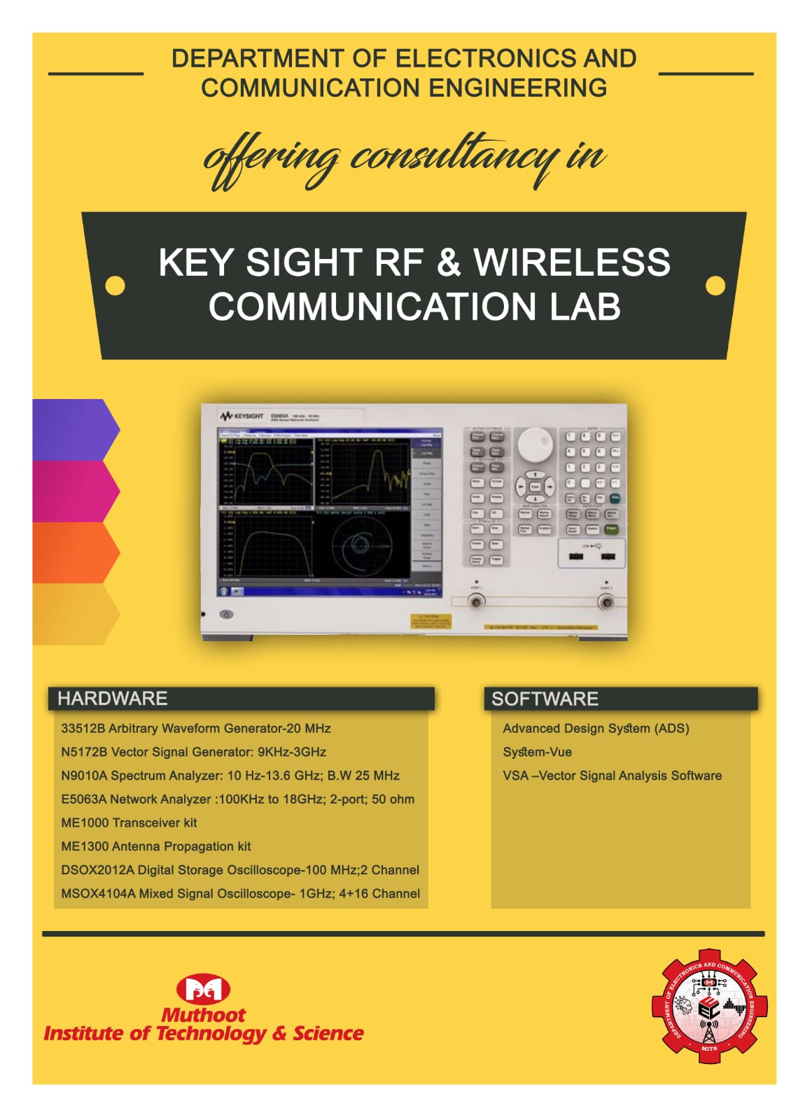
MITS has got an advanced and well equipped RF design laboratory covering design and verification of the concepts of modern digital communication systems that operates from KHz-GHz range. The equipments are upto the mark of industrial design and manufacturing standards thus making this lab an active launchpad for budding innovators and scientists. The lab includes experiments on applications of various communication protocols such as GSM/CDMA/WLAN/Bluetooth/Satellite/GPS etc., analysing different devices and components such as filters/amplifiers/antennas etc. which enables wireless communication effective, modulation techniques and Characteristics of microwave waveguide components. This lab is equipped with 13.6 GHz Spectrum analyser, 18 GHz Vector Network Analyser, Mixed Signal Oscilloscopes, Digital Oscilloscope, Arbitrary waveform generator, Function Generators, Transmitter and Receiver modules, Antennas, Modules for Digital Modulation and Demodulation techniques and Power Supply units.
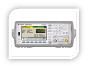
Arbitrary Waveform Generator (AWG) can generate any arbitrarily defined waveshape as their output along with standard waveforms. Our lab is equipped with AWG 33512B by Keysight Inc. The key features includes 16-bit resolution with 1 mVpp to 10 Vpp amplitude for greater amplitude accuracy; 1 MSa/channel standard waveform memory, optional 16 MSa/channel for long waveforms; USB, LAN (LXI-C), GPIB standard for quick and easy connectivity to PC or network; 2 channels for operation;wide bandwidth of 20 MHz; operating modes such as Continuous, modulate, frequency sweep, burst, output gate;Modulation types such as AM, FM, PM, FSK, BPSK, PWM, Sum (carrier + modulation); Standard waveforms such as Sine, square, ramp, pulse, triangle, Gaussian noise,PRBS (pseudorandom binary sequence), DC along with built-in and user-defined arbitrary waveforms.
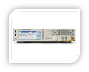
Signal Generator is used to generate repeating or non-repeating electronic signals in either the analog or the digital domain. It is generally used in designing, testing, troubleshooting, and repairing electronic or electroacoustic devices. Vector Signal Generators (VSG) are capable of generating digitally-modulated radio signals that may use any of a large number of digital modulation formats. Our lab is equipped with EXG-X series N5172B VSG from Keysight. Key features includes frequency range of 9KHz-3/6GHz; Output Power ranging from -144 dBm to +26 dBm; output digital modulation formats such as QAM, QPSK, FSK, BPSK, and OFDM; industry standard signals such as GSM, W-CDMA (UMTS), CDMA2000, LTE, Wi-Fi (IEEE 802.11), and WiMAX (IEEE 802.16).
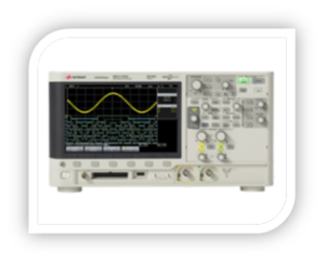
Digital oscilloscope or Digital Storage Oscilloscope (often referred to as DSOs) input a signal and then digitize it through the use of an analog-to-digital converter.Having the data in digital form enables the oscilloscope to perform a variety of measurements on the waveform. Signals can also be stored indefinitely in memory. Our lab is equipped with InfiniiVision 2000X series DSO X2012A by Keysight. The main features of this DSO includes 100 MHz bandwidth; 2 channels for operation; Maximum Memory Depth of 1 Mpts; Maximum Sample Rate of 2 GSa/s; 8 bit ADC; in built Digital Channels, 20 MHz Function Generator, 5-digit Counter, 3-digit DVM.
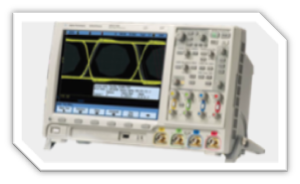
Mixed Signal Oscilloscope (MSO) has two kinds of inputs, a small number (typically two or four) of analog channels, and a larger number (typically sixteen) of digital channels.While oscilloscopes are the most commonly used test instruments in an R&D environment, sometimes 2 and 4 channel oscilloscope measurements are insufficient to monitor and test critical timing interactions between multiple analog and digital signals. This is where an MSO proves useful because it provides enough of the traditional logic analyzer measurement capabilities without adding the complexity often associated with a logic analyzer. The MITS RF design lab is equipped with InfiniiVision 4000 X series MSO X4104A by Keysight. The key features of this MSO includes Bandwidth of operation 1 GHz; 4 analogand 16 digital channels of operation; Isolate signals in seconds with exclusive Zone touch triggering; Capture more data with 4 Mpts memory and standard segmented memory.\
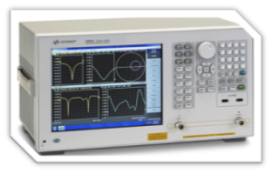
Network Analyzer measures the network parameters of electrical networks. Network Analyzersare commonly employed in measuring s-parameters because reflection and transmission of electrical networks are easy to measure at high frequencies. A Vector Network Analyzer (VNA) measures both amplitude and phase properties . Our lab is equipped with ENA series E5063A Vector Network Analyzer from Keysight. The key features includes 100KHz to 18GHz frequency range; 2-port, 50 ohm, S-parameter test set; finding S-Parameter, Return Loss, Time Domain, Insertion Loss/Gain; Dynamic Range 117 Db.
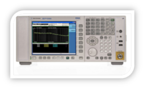
Spectrum Analyser measures the magnitude of an input signal versus frequency. The primary use is to measure the power of the spectrum of known and unknown signals. By analyzing the spectra, dominant frequency, power, distortion, harmonics, bandwidth, and other spectral components of a signal can be observed that are not easily detectable in time domain waveforms. These parameters are useful in the characterization of electronic devices, such as wireless transmitters. MITS RF Communication lab is equipped with EXA X-Series N 9010ASignal Analyzer (Spectrum Analyzer) from Keysight Technologies. Key features of this signal analyser includes Frequency range from 10 Hz to 13.6 GHz, Mixers to 1.1 THz; Maximum Analysis Bandwidth of 40 MHz; Bandwidth 25/40 MHz; Displayed average noise level DANL at 1 GHz is -163 dBm; Amplitude Accuracy ±0.27 dB.
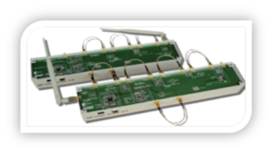
ME 1000 Transmitter – Receiver:
Transmitter is an electronic device which generates a radio frequency alternating current. When a connected antenna is excited by this alternating current, the antenna emits radio waves.In addition to their use in broadcasting, transmitters are necessary component parts of many electronic devices that communicate by radio, such as cell phones, wireless computer networks, Bluetooth enabled devices, garage door openers, two-way radios in aircraft, ships, spacecraft, radar sets and navigational beacons.
Receiver is an electronic device that receives radio waves and converts the information carried by them to a usable form. It is used with an antenna. The antenna intercepts radio waves (electromagnetic waves) and converts them to tiny alternating currents and extracts the desired information. Electronic filters separate the desired radio frequency signal from all the other signals picked up by the antenna. An electronic amplifier is used to increase the power of the signal for further processing, and finally the desired information is obtained through demodulation.
The RF transceiver kit consists of a transmitter unit and a receiver unit. The units are made up of various RF modules such as low noise amplifier, power amplifier, band pass filters, mixer, frequency synthesizer, antenna etc. to form both the transmitter and receiver sections of a superheterodyne system. MITS RF Communication lab is equipped with Transceiver kit ME 1000from dreamCatcher. The key features of this kit includes Frequency synthesizer output power of −4.5 dBm (typical); Frequency synthesizer frequency range from 816 MHz to 880 MHz for Tx/Rx; Antenna frequency range from 806 MHz to 960 MHz for Tx/Rx; Antenna length of 210 mm for Tx/Rx.